 Brian D. Wendt
The digital pins on the Arduino board can be set (with code) to output either HIGH (5V) or LOW (0V) — essentially ON or OFF. This is great for applications like blinking LEDs or activating relays.
But what if we wanted an output voltage somewhere in between 0V and 5V? This might be useful in applications like controlling the speed of a DC motor, or “dimming” an LED.
Well, the digital pins cannot directly produce an analog voltage; as we’ve said, they’re either HIGH or LOW. But it turns out we can simulate these “in-between” voltages using a technique called Pulse Width Modulation, or PWM.
First off, don’t panic. PWM sounds complicated, but as we’ll see, the concept is very simple, and the implementation is even easier, especially on the Arduino.
Let’s say we want to make an LED shine with half of its normal intensity when supplied with 5 volts. Since we can’t use the Arduino’s digital pins to directly supply 2.5V, we’ll “pulse” the output pin on and off — really fast. You may have noticed this effect when you played with the Arduino’s “Blink” sketch. If you blink an LED fast enough — that is, if the delay between blinks is short enough — the LED will appear to be lit continuously, but just a little bit dimmer than it was originally.
It’s easy to visualize this concept using the graphs below. When you plot voltage over time, you can see that the pin is pulsing between HIGH and LOW at regular intervals. Since this on-off pulsing is happening so quickly, the connected LED will “see” the result as a 50% reduction in the normal voltage (in this example), and will glow at roughly half its normal intensity.
We can vary the output voltage percentage (the “effective voltage”) by regulating — or “modulating” — the width of the pulse. For example, if we make the HIGH pulse 25% as “wide” (in time) as the LOW pulse, the LED will appear to glow with 25% intensity.
“Okay, great,” you’re saying, “But how do I do this on the Arduino?” Well, there are a couple of ways. First, you could write a sketch that blinks the LED between HIGH and LOW really fast, as we discussed above. However, this approach requires the full attention of the Arduino all the time; that is, if you want the Arduino to do anything else, you’ll be interrupting the pulse loop.
Luckily, the Arduino designers have already solved this problem for us with three dedicated pins and the analogWrite() command.
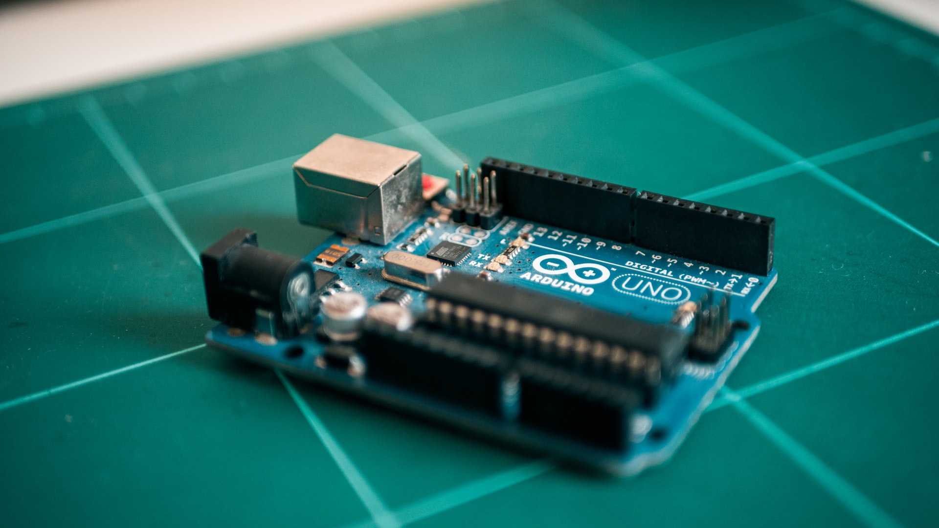
Notice on the Arduino board there are three digital pins (9-11) which are labeled PWM. Devices (like LEDs) connected to these pins can employ continuous pulse width modulation using only the analogWrite() command like so:
/*
 * A simple PWM example
 */

int pin = 11; // LED connected to PWM pin 11
int pulsewidth = 127; // Any value between 0 and 255

void setup() {
    // None required for analogWrite!
}

void loop() {
    analogWrite(pin, pulsewidth);
}
The example above should cause the connected LED to glow at about 50% intensity (255/2 = 127ish). Play around with the value of the pulsewidth variable and note the changes in LED brightness.
Now, let’s take this concept one step further. What if we varied the effective voltage to the LED over time? If we could devise a way to “fade” the pulsewidth from zero to 255 and back again, then the LED would pulsate, as in the video above. Here’s the code for that, using three LEDs this time, connected to pins 9-11:
/*
 * Pulsating LEDs with Pulse Width Modulation
 */

int green = 11; // Digital pin 11 - Green LED
int red = 10; // Digital pin 10 - Red LED
int blue = 9; // Digital pin 9 - Blue LED
int time = 5; // define delay element
int pulsewidth; // define pulsewidth (0-255)

void setup() {
    // None required for analogWrite!
}

void loop() {
    // slowly fade the LEDs to full brightness
    for (pulsewidth=0; pulsewidth <= 255; pulsewidth++) {
        analogWrite(green, pulsewidth);
        analogWrite(red, pulsewidth);
        analogWrite(blue, pulsewidth);
        delay(time);
    }
    // slowly dim the LEDs
    for (pulsewidth=255; pulsewidth >= 0; pulsewidth--) {
        analogWrite(green, pulsewidth);
        analogWrite(red, pulsewidth);
        analogWrite(blue, pulsewidth);
        delay(time);
    }
}
Cool, huh?
References
- Tom Igoe, “Analog Output“
- Sebastian Tomczak, “PWM and You: A Quick Primer”
Author’s Note
This article was originally published on Principia Labs.
 CATO: Catastrophic Engine Failure