 Brian D. Wendt
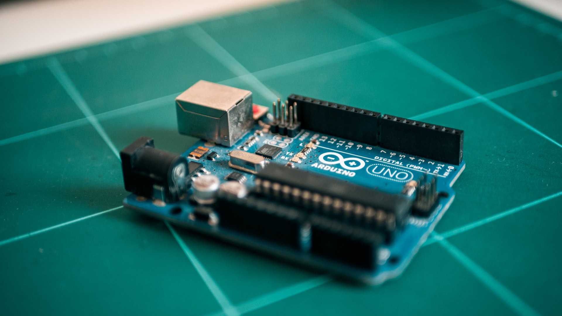
One of the cool features of the Arduino platform is its ability to talk to other electronic devices using standard protocols. The big draw of physical computing, in my opinion, is the power it gives you to affect a limitless range of real-world objects with your PC, rather than just boring old monitors and printers.
This short tutorial will demonstrate one way to use Arduino to control a servo motor with a PC, using a USB cable and the Arduino’s serial library. It will in no way attempt to be an introduction to asynchronous serial communication, since such topics are better addressed elsewhere.
RC servos are comprised of a DC motor mechanically linked to a potentiometer. Pulse-width modulation (PWM) signals sent to the servo are translated into position commands by electronics inside the servo. When the servo is commanded to rotate, the DC motor is powered until the potentiometer reaches the value corresponding to the commanded position.
A standard RC servo has three wires: Ground (black or brown), Power (red) and Control (orange, yellow or white) and will move based on pulses sent over the control wire. The control pulses set the angle of the servo horn. The servo expects a pulse every 20 ms in order to gain correct information about the angle. The pulse width maps directly to the servo angle. Most servos will rotate 180°, and expect pulse widths between 1-2 ms or so.

Image credit: Society of Robots
This project uses a JR Sport ST47 Standard servo, which accepts an input voltage between 4.8 and 6 volts — perfect for the Arduino’s 5V output pin. Connect the servo’s brown and red wires to the Arduino’s Gnd and 5V POWER pins, respectively (colored orange in the diagram below), and connect the servo’s orange control wire to the Arduino’s digital pin #2 (on the green row in the diagram).

Image credit: Arduino.cc
Using the Arduino IDE, upload the following code to the board, which will allow you to control the position of the servo over a serial connection. Pay particular attention to the variables minPulse and maxPulse, as these define the min and max pulse widths for your servo. As mentioned earlier, most servos expect a pulse width between 1-2 ms, however, a range of 0.5 ms to 2.5 ms (500-2500μs) may be required, depending on your servo. Experiment as necessary.
/* * NewSerialServo * ————– * Servo control from the Serial port * * Alteration of the control interface to use < and > keys * to slew the servo horn left and right. Works best with * the Linux/Mac terminal “screen” program. * * Created 10 December 2007 * copyleft 2007 Brian D. Wendt * http://principialabs.com/ * * Adapted from code by Tom Igoe * http://itp.nyu.edu/physcomp/Labs/Servo */
/** Adjust these values for your servo and setup, if necessary **/ int servoPin = 2; // control pin for servo motor int minPulse = 600; // minimum servo position int maxPulse = 2400; // maximum servo position int turnRate = 100; // servo turn rate increment (larger value, faster rate) int refreshTime = 20; // time (ms) between pulses (50Hz)
/** The Arduino will calculate these values for you **/ int centerServo; // center servo position int pulseWidth; // servo pulse width int moveServo; // raw user input long lastPulse = 0; // recorded time (ms) of the last pulse
void setup() { pinMode(servoPin, OUTPUT); // Set servo pin as an output pin centerServo = maxPulse - ((maxPulse - minPulse)/2); pulseWidth = centerServo; // Give the servo a starting point (or it floats) Serial.begin(9600); Serial.println(“ Arduino Serial Servo Control”); Serial.println(“Press < or > to move, spacebar to center”); Serial.println(); }
void loop() { // wait for serial input if (Serial.available() > 0) { // read the incoming byte: moveServo = Serial.read();
// ASCII '<' is 44, ASCII '>' is 46 (comma and period, really)
if (moveServo == 44) { pulseWidth = pulseWidth - turnRate; }
if (moveServo == 46) { pulseWidth = pulseWidth + turnRate; }
if (moveServo == 32) { pulseWidth = centerServo; }

// stop servo pulse at min and max
if (pulseWidth > maxPulse) { pulseWidth = maxPulse; }
if (pulseWidth < minPulse) { pulseWidth = minPulse; }

// print pulseWidth back to the Serial Monitor (uncomment to debug)
// Serial.print("Pulse Width: ");
// Serial.print(pulseWidth);
// Serial.println("us");   // microseconds
}
// pulse the servo every 20 ms (refreshTime) with current pulseWidth // this will hold the servo’s position if unchanged, or move it if changed if (millis() - lastPulse >= refreshTime) { digitalWrite(servoPin, HIGH); // start the pulse delayMicroseconds(pulseWidth); // pulse width digitalWrite(servoPin, LOW); // stop the pulse lastPulse = millis(); // save the time of the last pulse } }
Once you’ve got the code uploaded, you’re ready to go! You can send and receive serial data using the Arudino IDE’s Serial Monitor, or you can use a Linux terminal (as in the video) with the screen command, like so:
screen /dev/ttyUSB0 9600
The first element of the screen command specifies the USB port, and the second the serial baud rate (9600). You may need to run ls /dev/tty* to find the correct USB port on your machine.
The theory behind this project can be extended to include a graphical user interface on the PC to control the servo motor, and maybe even the addition of an Ethernet connection for networked control.
References
- Wikipedia, “Servomechanism“
- Society of Robots, “Actuators and Servos“
- ITP Physical Computing, “Servo Lab“
- ITP Physical Computing, “Serial Lab“
- Tom Igoe, “Serial Communication“
- Tom Igoe, “Interpreting Serial Data”
Author’s Note
This article was originally published on Principia Labs.